

Petrol pump overhaul
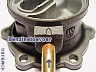
Pump body A. Pierburg K.G. Neuß.
Arrow indicates the flow of gasoline / petrol.
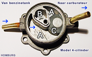
Operation of the diaphragm pump with two valves
The drive of the petrol pump is provided by the oil pump. Which is directly driven by the crankshaft with a gear ratio of z = 31 (crankshaft) and z = 59 (oil pump) and the delay is 0.525. The motion is thus very similar to the ignition cycle. In two revolutions of the crankshaft, the operating rod moves slightly more back and forth than once (1.05). Because of the radial eccentric movement on the oil pump, the diaphragm moves up and down in the fuel pump. Overall result is 4 mm.
With the downward movement of the diaphragm, petrol is moved from chamber A, through the nylon filter, into chamber B through the metal valve B-1. The room D (bottom) is filled up with petrol. With the upward movement by the pressure, the metal valve B-1 closed and valve C-1 (pertinax) opened, allowing the fuel through the exhaust pipe to the carburetor (s) are pressed.
For old model fuel pump is the supply-direction of fuel indicated by an arrow on the cast house (see left sidebar). The new types of fuel pumps (steel) have the fuel supply to the carburetter at the top.
Overhaul
Minor maintenance
Remove the Allen screw M5 x 18 + fiber ring 5 mm and remove the upper steel cover cap. Make sure the gasket 38 x 44 x 0.8 mm is not damaged.
When the gasket is damaged, fit a new gasket.
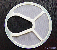
Clean the fuel filter and replace a damaged one, and replace the cover cap.
Major maintenance - diaphragm valve maintenance and renewal
Remove the fuel hose from the inlet and outlet tube and plug the hoses.
Clean the fuel pump clean, and the crankcase clean.
Remove the two mounting schoeven, twist the gas pump a quarter turn left and pull the rod away. Make a sketch how the diaphragm is mounted.
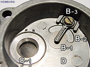
For the bottom: unscrew six M5 x 12 Allen screws and remove the metal base, the pressure spring and the diaphragm. Make the metal base clean and check the flatness. Often the surface for the diaphragm is curvatured, so the diaphragm can not securely fastened. Restore it before installing the diaphragm or replace the metal bottom.
The springy metal cover B-1 is easy to disassemble and clean by removing screw B-3. The cup-shaped room B-2 promotes the fuel supply from room B, while a vacuum through the diaphragm. B-1 valve closes the inlet hole, 6 mm in diameter.
Door C-1 can also leak. Check it by blowing into the exhaust tube. Any leakage must be solved. It is possible to disassemble the valve and pertinax plate renewal. This is not easy and should be done with proper tools. Rather not remove the pertinax valve. Clean the pertinax valve plate thoroughly with a lint-free cloth.
Before assembly, clean all parts. Place the diaphragm in the correct position (note there are two models of diaphragms) and fasten the 6 screws when the diaphragm in the neutral position (spring is stretched). Assemble the other parts.
Diaphragm
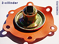
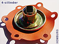
The diaphragm of the Prinz 4 and the 4-cylinder models are different.
2-cylinder: the long side of the rectangular steel carrier:
In one line with two screw holes.
4-cylinder: the long side of the rectangular steel carrier:
between the two holes. See the 2 photos on the left sidebar.
2-cylinder: when you look at the pump at the bottom, the steel rectangular slot of the diaphragm is at odds with the two mounting holes.
4-cylinder: when you look at the pump at the bottom, the steel rectangular slot of the diaphragm is in line with the 2 mounting holes.
Mounting on the crankcase
Use new O-rings 20 x 28 for mounting the fuel pump to the cranckcase. Rotate the crankshaft until the excenterstang at the highest point. Apply pressure to the inlet tube (use a pump) while keeping the exhaust tube closed with a finger so that the diaphragm is pressed down. Replace the fuel pump with spacers and O-ring(s) directly into place, turn the pump a quarter to the left of his original position, carefully engage the tongue of the control rod into the diaphragm by turning the pump body back 90 degrees to the right. Remove the finger and the pump is drawn into the crankcase. Place the two spacers and secure the fuel pump with the 2 mounting screws (M5) and spring washers. Connect the fuel hoses and secure them both with hose clamps. To prevent the fuel pump only pumps air in the beginning, the following can be done. Remove the hose from the carburetor, with the mouth suck up petrol... Extend the fuel hose with a piece of clear hose (with nipple) so you do not drink gasoline... Turn the fuel hose to the carburetor with a hose clamp and use a safety bracket...
New type fuel pump
From 1971 new types of fuel pumps are installed.
For the 2-cylinder 041-08-01-501-000 + No longer spacers.
For the 4-cylinder 782-08-501-01-000 + No longer spacers.
The fuel filter can be cleaned, but the diaphragm can not be replaced.
If the diaphragm is broken, the pump must be replaced.
The petrol supply (inlet) is connected to the tube of the cover cap.
The fuel runs first through the filter and then into the pump part.
Extra fuel filter
Because the filter in the fuel pump is comparatively open, it can fairly easily by small dirt. The jets become clogged thereby. For the stationary spoeier a problem, making the engine run idle poorly or even stop. This happens often with an empty fuel tank. There is rust inside the tank mixed with petrol. An additional filter is a solution. If an extra fuel filter is placed in the hose, you can place it easely between the fuel pump and carburetor. Another option: place the filter between the tank and the fuel pump so the fuel pump remains clean inside too.
Check that the pump provides adequate pressure.
Operating pressure 1.10 to 2.10 lb/sq inch Prinz 4.
Operation pressure 2.84 to 3.55 lb/sq inch 1000 (0.20 to 0.25 kg/sq cm at an engine speed of 4000 rev/min)
Fuel hose from the fuel tank - assembling fuel tank into the car
When a fuel tank in the luggage area is placed, special attention should be given to the small piece of fuel hose from the fuel tank to the nylon fuel hose. It is a classic problem in assembling this piece of tubing pinched a nod upwards and therefore have an insufficient fuel flow. Even after a nod and restoration of the hose, after years, by aging of the rubber hose it will kink.
The phenomenon occurs, the lack of petrol, (the tube is squeezed) and quickly turns off the engine. Check the tube even after some years and the best prevention is simply to renew the tube. The lower steel protector must be removed.
CAUTION
- When the fuel tank must be removed, first disconnect the battery.
A small spark is enough for a large fire. - Work safely when working on the fuel circuit,
keep a fire extinguisher nearby.
- Do not use water for gasoline/petrol fire.