
Cylinder head removal and refitting Prinz 4
Determine first what the problem is before dismantling
the cylinder head. Measure the compression, the oil
usage and assess the exhaust gas.
The cylinder head can be removed without special tools.
Only a brass drift of 10 mm is necessary to drive outwards the eccentric shaft.
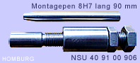
Special tools necessary for refitting
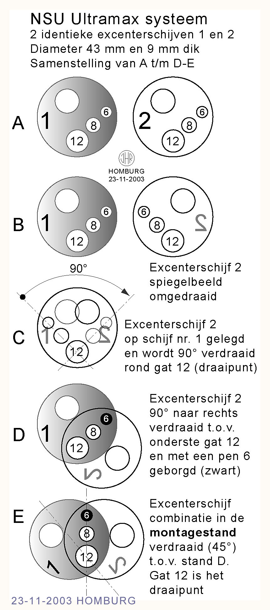
A trigger for assembling the eccentric shaft, NSU nr. 40.91.00.906 and a pin tool for aligning of the eccentric discs and the balance weight. The assembly trigger is necessary to ensure that the small ball bearing remains in good condition.
An assembly pin d = 8H7 with a tapered point. Total length 90 mm.
A special punch of brass d = 20 mm and long 25 cm. The eccentric shaft should be lightly punched in combination at the same time of strengthen the trigger.
Instruction to remove and refitt the cylinder head while the engine is in the car
- Disconnect the battery terminals
- Remove the air cooling ducts
- Mark the 2 spark plug cables and remove the cables and spark plugs
- Remove the air filter and the carburetter
- Remove the exhaust system
- Remove the aluminium rocker cover
- Remove the Dynastarter cover
Assess the situation under the rocker cover and take photographs for easy replacement. Use identification marks on the rocker arms and the other parts with scratches of store them in a special box with compartments.
Care has been taken to replace the parts in the original position.
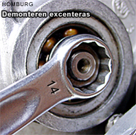
Slacken all the M10x1 nuts and adjustments crews of the rockers.
Use a ring spanner 14 mm and a large screwdriver.
Important
Rotate the crankshaft clockwise until the second piston (left side) is at TDC position. Both rockers do have clearance. The eccentric weight indicates down.
Close the openings between the eccentric drive rods with pieces of clothing to prevent that any component can fall down into the engine.
Removing the ultramax system and cylinder head
Step 1
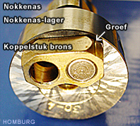
Remove the 4 circlips using a pair of circlip pliers with suitable points and remove the 2 shafts using a soft metal drift. Take care of the 4 shim washers and their position and the 2 springs. Release the large circlip at the inner side of the camshaft bearing using 2 screwdrivers and push the camshaft bearing from his fitting. Draw away the camshaft including the connection piece gently from its bronze bearing of the cylinder head and notice the position of the long cam pin inside the eccentric shaft. Watch the position of the short cam pin inside the camshaft and the connection piece of bronze. Make a sketch of the situations. Remove the thrust pin and spring from the eccentric shaft.
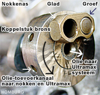
At the centre you see the shaped thrust pin and behind the pin the spring. The shaped thrust pin ensures that the oil which is pumped into the camshaft by means of this thrust pin also lubricates the eccentric and drive components. Check the surface of the thrust pin (the camshaft site) witch should be flat.
Left of the thrust pin you can see the oil impression of the connection piece. Check by assembly the clearance between connection piece and cam pin, these must turn around without clearance.
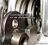
The balance weight of the eccentric system should be positioned down to prevent that the distance ring can fall down in the engine.
Step 2
 Turn the nut M10x1 apart from the eccentric shaft with a appropriate ring spanner 14 mm and remove the nut and the spring washer.
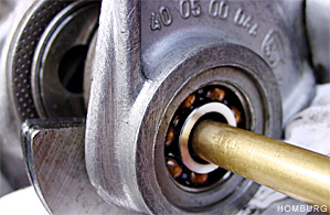 Drive the eccentric shaft very quiet using a brass drift outwards the bearing and distance ring until the end of the balance weight plate. Keeps the drift as long as possible in that position and slowly remove the balance weight and distance ring outwards. Simultaneously withdraw the drift.
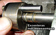 Remove the eccentric shaft further with the drift and lift it away including the long cam pin (d = 8 mm and long 50 mm). See the photograph.
Step 3
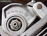
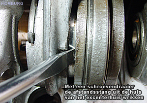 Slacken the two nuts of the eccentric bearing link with a ring spanner 11 mm and lift the casing upwards. Take care or the needle bearing and keep it free from dust and dirt. (Needle bearing 38 x 43 x 17 INA F-4080 02/E7)
Step 4
Move the 2 drive rods in the correct position and rotate the
2 eccentric discs in the correct assembly position. Sketch the situation of the eccentric discs (see also the photograph of the assembly position) to help when you refitting it again.
Rotate the crankshaft approximately 80 degrees clockwise until both drive rods upper points stands on equal altitude. After removing the eccentric discs you have to MARK the eccentric discs to ensure a correct reassembly.
Step 5
Use a ring spanner to slacken off the 6 cylinder head gasket ring retaining nuts and remove them. Refer to the picture and slacken the cylinder head retaining nuts in the order shown in the picture, half a turn at a time, and them completely unscrew, also the two M7 bolts. Hereafter the cylinder head can be removed carefully by lifting it away. Use a soft faced hammer or a large screwdriver to break the seal.
Important note
Do not rotate the crankshaft any more. If the crankshaft is rotated in any other given position it is absolutely impossible to reassemble the eccentric discs. In principle the drive rods must be standing in the highest position.
Cylinder head overhaul remarks
Cylinder head
- Clean the cylinder head
- Remove all traces of carbon and old gaskets
- Remove all carbon deposits from the combushion chambers and valve ports
- Check the thread for the spark plugs
- Valve guides must be replaced
- The valve seats must be reconditioned at the correct angles after the fitting of new valve guides
- Clean the seats of the cylinder head retaining nuts
- Check the mounting surface of the cylinder head (max. skimmed off -0,3 mm)
- Assemble new inlet valves and exhaust valves
- Check the camshaft and the connection piece
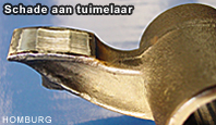
- Check the rockers
- Check the bearing of the camshaft
- Check the needle bearing surface of the eccentric shaft
- Check the ball bearing 12 x 32 x 10 and the needle bearing
- Check all oil holes
- Check the thread of the 6 studs M8x1of the exhaust heat exchanger
- Use the special Ensatz-thread bush to restore the thread
- Bay a complete gasket set of the cylinder head
CYLINDER and PISTONS
- Overhaul also the cylinders
- Honing the cylinder bore
- This operation should bring the bore size to correspond the
standard size of the piston - Otherwise you need oversized pistons and piston rings
- Measure the slot cap of the piston rings
- It is always better to replace the piston rings anyway
Cylinder head refitting
Assemble all moving components with engine oil.
The connection piece also with Molykote grease.
Clean the thread of the studs M10 before mounting the cylinder head and check
the quality of the nuts (replace these if necessary).
Clean all parts, check the 2 dowels of the cylinder head - cylinder and oil feed sealing O-ring (oil bore for camshaft and eccentric system), fit a new cylinder head gasket to the cylinders and place the cylinder head.
A torque wrench is necessary
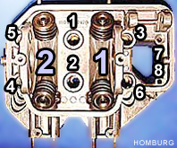 Tighten the cylinder head nuts in order shown on the left photograph to a torque wrench with a setting of 25 lb ft (35 Nm). The 2 bolts M7 should be tighten normally. Fit the 6 cylinder head gasket sealing ring retaining nuts. Cylinder head nuts and bolts retighten after 500 km and 2.500 km. See retighten cylinder head nuts.
Check the position of the drive rods
in combination of the eccentric discs, see photograph below.
Close the openings between the eccentric drive rods with pieces of clothing to prevent that any component can fall down into the engine.
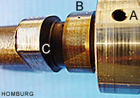
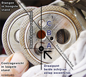 This is the correct assembly position of both drive rods and eccentric discs before inserting the eccentric shaft. The eccentric shaft fits in hole A (diam. 12 mm). The long cam pin (8 mm long 50 mm) meets hole B. The small cam pin is fixed in hole C.
The both eccentric discs are fixed when the eccentric shaft is fitted.
The eccentric disc system is rotating along shaft A.
Mounting the eccentric discs
Step 1
The drive rods must be standing in the highest position. Push the eccentric discs into their bronze bushings. Rotate the crankshaft counter clockwise about 80 degrees to the TDC position. Adjust the drive rods as shown in the photograph above. Crankshaft at TDC position, the 2e cylinder (left) at ignition position.
This is the only way to assemble the eccentric shaft correctly
Step 2
Push the eccentric bearing link down in its normal position and refit the distance rod over the bushing. Keep the needle bearing free of dirt.
Step 3
Remove the original long cam pin carefully from the eccentric shaft. Mark the cam pin to ensure correct replacement in its original position. Check by assembly the clearance between connection piece and cam pin, the parts must turn around without clearance. Smear the connection piece and cam pins with a good quality grease.
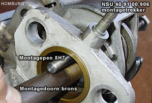 Press the assembly pin tool into the eccentric shaft and push the eccentric shaft (assembly pin on top) from the cylinder head inside to the eccentric discs.
Above the heavy drift in the photograph you see the assembly tool 8 H7.
Step 4
Position the drive rods and eccentric discs in the position as shown in the photograph. Press the eccentric shaft into the discs, but not too far, because the balance weight and distance ring must be placed.
Step 5
 Place the distance ring into the round shaped area of the balance weight. Move the balance weight and ring into position and press the assembly pin through the hole of the balance weight. Draw the assembly pin backwards INTO the hole. Move the distance ring into position and push the eccentric shaft carefully and slow through the holes using a heavy bronze assembly drift. Adjust continuously the position of the distance ring.
Heat preferably the inside ring of the roll bearing with an electric heater for a smooth assembly.
Step 6
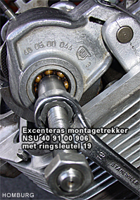
Press and push the eccentric shaft as far as possible into the roll bearing. Screw the assembly tool 906 to the shaft when there is about 5 mm thread outside the ball bearing. Draw the eccentric shaft firm into its seat position with the tool nut 19 mm. Use if necessary the heavy drift on the other site for easy fitting. Screw the assembly tool 906 meanwhile as far as possible onto the tread end.
Step 6 WARNING assembly tool 906
Do not screw the assembly tool 906 through the ball bearing to get the treated shaft early. The passage trough the ball bearing is too narrow. In some cases the draw pressure is so extreme that the treated part of the assembly tool will expand. That results in a vary serious problem. The assembly tool is badly fixed into the ball bearing.
Step 7
After complete refitting of the eccentric shaft, the assembly tool should be replaced by the original long cam pin. Assemble the cam pin with oil.
Step 8
Place the spring washer and tighten the nut firmly with a ring spanner 14 mm. Tighten the 2 nuts of the camshaft drive casing with a ring spanner 11 mm.
Step 9
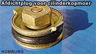
Place the sealing plug with the spring and some Molykote grease and check the free movement by pressing it.
Step 10
Carefully place the camshaft into its position and grease the connection piece.
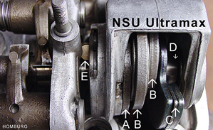 The system ready for use
A Distance rod
B Drive rods
C Counterweight
D Distance ring
E Connecting piece
Refit all other parts in revers sequence
It is important to oil and grease the moving or rotating parts before closing the cylinder head cover. Take special attention to refit the rocker cover gasket. Clean all contact surfaces and use small amount of a good quality sealing compound Elring Dirko HT (red). When the engine runs and at temperature you need to retighten the 2 cylinder head cover nuts.
Remarks
- The crankshaft rotates clockwise
- The camshaft rotates counter clockwise
- The crankshaft makes 2 rotations for the 4 stroke cycles
- Retighten cylinder head nuts at 500 km and 2.500 km
General preparation
- Disconnect the battery for safety reason
- Remove all other components to give access to the cylinder head cover
- Slacken the 6 nuts of the exhaust system
Special preparation
- Slacken the nuts of the rockers
- Remove the rocker shafts and other components (mark the positions)
- Remove the 6 cylinder head gasket ring retaining nuts
- Slacken the 2 nuts M7 of the camshaft drive casing
- Retighten cylinder head nuts
Slacken the cylinder head nut a quarter counter clockwise and retighten the nut again with a torque wrench at a setting of 25 lb ft (35 Nm). Do this operation for the 6 nuts in the fastening sequence. The 2 bolts M7 should be slacken and retightened firmly. Fit the 6 cylinder head gasket sealing ring retaining nuts and check the sealing ring. Retighten the 2 nuts M7 of the camshaft drive casing.
General refitting
- Retighten the 6 nuts of the exhaust system
- Reassemble all other components
- Check the rocker clearances