Clutch of the 4 cylinder engine
Changing the driven plate and other parts of the clutch.

Tools
- Allen key 10 mm
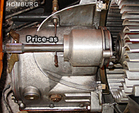
- Bolt M8 x 50 (removing the prise-as of clutch shaft)
- 2 screwdrivers strong
- Allen key 5 mm with T-handle
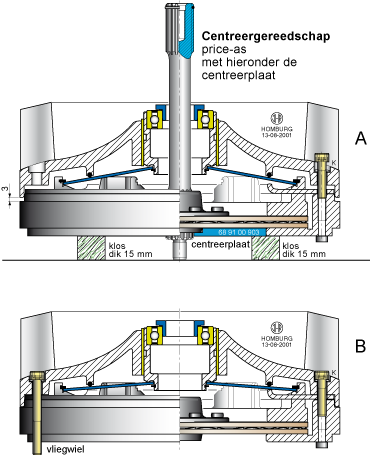
- Centralizing disc nr. 68 91 00 903 and prise-as or clutch shaft
Materials
- New driven plate
- Molykote grease (for splines of prise-as of clutch shaft)
- Bearing grease (bearing assembly)
- Socket-headed bolts M6 x 53 (6x) and M6 x 25 (3x)
- Loctite 243
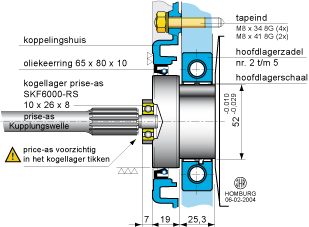
- Oil seal 35 x 52 x 7
- O-ring 35 x 41 for cover plate
- Release lever and securing springs
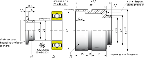
- Bearing 6005 2RS 25 x 47 x 12
Remove the clutch from the engine
- Disconnect the battery for safety reason
- Remove the air junction duct and the inlet duct
- Disconnect the operating cable and release lever
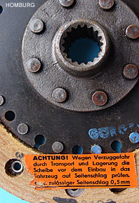
- Remove the snapring and the cover plate
- Unscrew the large plug SW10 Allen key
- Screw a M8 x 50 bolt into the clutch shaft and lever the clutch shaft out
- Unscrew the 2 holders of the coverplate and remove the cover plate by sliding it around from the gearbox
- Unscrew the 6 socket-headed bolts M6 x 53 mm
- Do not unscrew the 3 socket-headed bolts market with the letter K
- Draw the clutch away from the flywheel. Use a screwdriver for help
- Use a piece of cloth or gloves because the blades are sharp
Dismantling the clutch
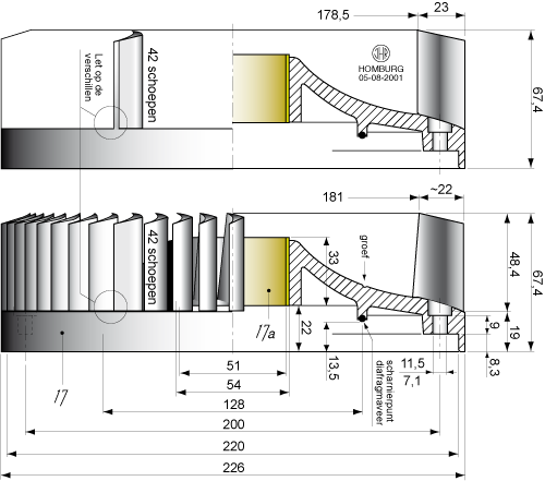
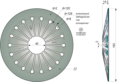
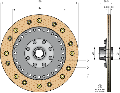
All the parts that are fixed together must be marked before dismantling. Use a centre-punch. Unscrew the 3 socked-headed bolts, near the K marks, and lift off the impeller. Remove the snap ring and lift off the diaphragm spring. The counter plate and the pressure plate can be removed. The driven plate can be lifted out of the clutch. The driven plate friction linings must be renewed. Clean all the clutch parts.
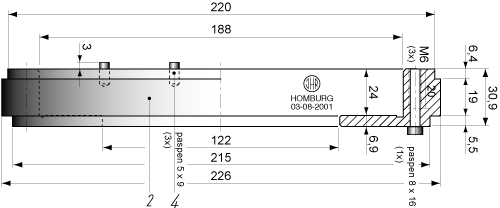
Parts of the clutch


Assembly of the clutch
Drawing A = starting assembly
Drawing B = assembled situation
Assembly Steps
Lubricate all bearing points lightly with Molykote grease.
- 1. Place the centralizing disc on 2 parts of wood and place clutch sleeve
- 2. Place the driven plate and the clutch shaft for centralizing
- 3. Place the pressure plate and mount the counter plate
- 4. Place the diaphragm spring and clutch release bearing
and fit the snap ring accurately - 5. Assemble the cooling impeller in the right position with 3x M6 x 25
- 6. Assemble the clutch to the flywheel with 6x M6 x 53 mm 8G
and optional use Loctite 243
Warning
THE CLUTCH DRIVEN PLATE MUST BE CENTRALIZED ACCURATELY IN THE CLUTCH. When the driven plate in not correct centralized it is impossible to fit the clutch shaft.
Clutch release bearing
Assembly to the engine
The clutch is reassembled in the reverse order of removing. Lubricate the clutch shaft with Molykote grease and press it in position. If the clutch shaft is difficult to press use the release lever slightly so that the splines of the clutch shaft can align. Do it at the same time: constant pressing (or hammering soft) the clutch shaft and slightly release the lever.
Clutch shaft
![]()
Remarks
- Check the diaphragm spring
- Check the clutch release bearing 6005 2RS 25 x 47 x 12
- Check the release lever contact surface / pressure ring
- Check the oil seal 35 x 52 x 7 from the gearbox
- Check the sealing O-ring 35 x 41 of the cover plate
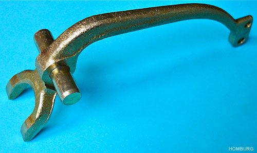
Release lever